$\setCounter{0}$
Part 1: The wave vector
Part 2: The interface
Part 3: The s-polarization
Part 4: The p-polarization
Part 5: Multilayers
Although we have already finished with what was promised at the beginning of this series – that is, we have derived the Fresnel’s coefficients for isotropic semi-infinite \(\varepsilon\mu\) medium in vacuum – we can now, with little effort, generalize the findings for a multi-layered system on semi-infinite substrate and surrounded by transparent dielectric medium. We will assume that the ambient medium is simple transparent dielectric with real \(\varepsilon_{a} > 0\), and our films and substrate consist of isotropic \(\varepsilon\mu\) materials.
Multilayer stack
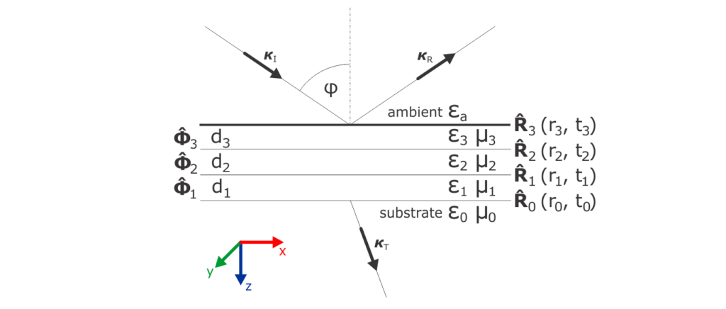
The following sketch presents such multilayer with three films on substrate, but our formalism can be easily extended for any finite number of layers.

We will be indexing our layers with \(j=0..3\), so the substrate response functions will be denoted as \(\varepsilon_0\), \(\mu_0\), not to be confused with vacuum permittivity and permeability constants.1 The ambient properties should have, technically, index \(j=4\) here, i.e \(\varepsilon_4 \equiv \varepsilon_{a}\), and \(\mu_4 \equiv \mu_{a} = 1\). The index \(j\) also belongs to thickness \(d_j\) of the particular layer and identifies the interface on top of that layer. The meaning of the symbols \(\mathbf{\hat{R}}_j\), \(\boldsymbol{\hat{\Phi}}_j\) will become clear below. We also illustrated the incident, \(\boldsymbol{\kappa}_I\), and reflected, \(\boldsymbol{\kappa}_R\), waves, together with the final transmitted wave, \(\boldsymbol{\kappa}_T\), which travels into the semi-infinite substrate.
Wave vectors in layers
In the transparent ambient, we can well define the angle of incidence \(\varphi\) and calculate the constants \(q = n_{a}\cos{\varphi}\) and \(\xi = n_{a}\sin{\varphi}\), where \(n_{a} = \sqrt{\varepsilon_{a}}\) is the ambient refractive index. Most typical scenario is, of course, vacuum or air ambient with \(n_a = 1\), but apart from that, we could be having some glass prism or immersion liquid medium with \(n_a > 1\) on top of our sample. Important point here is that \(\xi\), the x-component of the wave vector is conserved across all interfaces, i.e. remains real and non-negative. Then we can immediately calculate \(\kappa_j\), the z-component for any layer, inc. the substrate:
|
\( \begin{align}\label{eqKappaj} \kappa_j = \sqrt{\varepsilon_j \mu_j – \xi^2}, \end{align} \) |
which is valid also for the ambient, where \(\kappa_4 \equiv q\). Now we should consider again which root should be taken. In fact, for all the films and given \(\xi\), there are two possible wave vectors, one with \(\kappa_j\) and one with \(-\kappa_j\). The letter belongs to a wave reflected from lower interface and propagating upwards. We will choose the down-propagating wave vector component \(\kappa_j\) based on the imaginary part of the square-root, which must be positive. In case both \(\varepsilon_j\) and \(\mu_j\) are real, negative, and the argument of the square-root remains positive, we have to choose the negative real root as \(\kappa_j\), since we have negative refraction.
General Fresnel’s coefficients
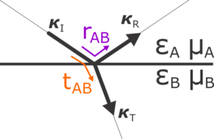
Now we will write the Fresnel’s coefficients for any interface between medium A and medium B, as schematically sketched below.

Note that A is the upper medium and B the lower, so when compared to the first figure in this post, we should not confuse the indexing. For example, the topmost interface will have \(A=4\) and \(B=3\), etc.
|
\( \begin{align} \begin{aligned} &\text{p-polarized}\quad &r_{xAB} &= \frac{\varepsilon_A \kappa_B – \varepsilon_B \kappa_A}{\varepsilon_A \kappa_B + \varepsilon_B \kappa_A}, &t_{xAB} &= \frac{2 \varepsilon_A \kappa_B}{\varepsilon_A \kappa_B + \varepsilon_B \kappa_A}, \\ \\ &\text{s-polarized}\quad &r_{yAB} &= \frac{\mu_B \kappa_A – \mu_A \kappa_B}{\mu_B \kappa_A + \mu_A \kappa_B}, &t_{yAB} &= \frac{2 \mu_B \kappa_A}{\mu_B \kappa_A + \mu_A \kappa_B}, \end{aligned}\label{eqsFresnelsGeneral} \end{align} \) |
where we labeled the coefficients with \(x\) and \(y\) to highlight that we are using our definitions in terms of the in-plane, \(x\) and \(y\), components of the electric field.
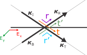
We should notice that \(r_{AB} = -r_{BA}\), i.e. that Fresnel’s reflection coefficient from the other side of the interface is exactly opposite, and that is true for both polarizations. Let’s simplify our notation again, and mark the reflection coefficient from above as \(r\), the reflection from below as \(r’\), the transmission from top as \(t\), and transmission from below upwards as \(t’\).
So we have \( r’ = -r \), and also \(1+r=t\), as well as \(1+r’ = t’\), valid for both polarizations, which can be put together to obtain \(1-r^2 = tt’\). This identity we will use in a moment.
Interface matrix
When we look at any of the interfaces, we will see that now we have to match four waves, \(\boldsymbol{\kappa}_I\), \(\boldsymbol{\kappa}_R\), \(\boldsymbol{\kappa}_T\) and \(\boldsymbol{\kappa}_B\) (\(B\) as back-propagating wave). The wave vectors all share the same x-component \(\xi\), since they all originate from the same topmost incident wave. The \(\boldsymbol{\kappa}_B\) is just reflected from some interfaces below. So in each layer, the electromagnetic field is composed of two waves for single polarization (we treat the polarizations separately here), one propagating down with the pre-calculated z-component \(\kappa_j \) (eq. \eqref{eqKappaj}) and other propagating up with \(-\kappa_j \).
Remember that the basic optics textbook explanation of thin film interference would discuss multiple reflections, which form infinite geometric series that gets eventually summed into single term. What we are developing here is the standard transfer matrix formalism, which is completely compatible, but we start from the idea that we have already only the pair of down and up propagating modes in any layer, and look for the linear coupling coefficients to match the waves on the interfaces.

On each interface, the tangential, x- or y-components of the electric field amplitudes must satisfy the continuity condition. In the following, we drop the corresponding index \(x\) or \(y\), since the formulas are valid for both polarizations:
\(
\begin{align}
E_I + E_R = E_T + E_B.
\end{align}
\)
We will reuse the already derived Fresnel’s coefficients, and write the amplitude \(E_R\) of the reflected wave as composed form the reflected part of the incident wave \(E_I\) and part of the \(E_B\) wave transmitted from below:
\(
\begin{align}\label{eqErEiEb}
E_R = rE_I + t’E_B.
\end{align}
\)
Also the total \(E_T\) is sum of the transmitted part of the incident wave \(E_T\) and back-reflected part of \(E_B\):
\(
\begin{align}\label{eqEtEiEb}
E_T = tE_I + r’E_B.
\end{align}
\)
We will want to express the fields above the interface, \(E_I\), \(E_R\) as combination of the waves below, \(E_T\), \(E_B\). So from \eqref{eqEtEiEb}, using \(r’ = -r\),
\(
\begin{align}\label{eqEiEtEb}
E_I = \frac{1}{t} (E_T – r’E_B) = \frac{1}{t} (E_T + rE_B),
\end{align}
\)
which we directly plug to \eqref{eqErEiEb}
\(
\begin{align}\label{eqErEtEb}
E_R =\frac{r}{t}(E_T + rE_B) + t’E_B = \frac{1}{t} (rE_T + r^2E_B + tt’E_B) = \frac{1}{t} (rE_T + E_B ),
\end{align}
\)
where we used the identity \(r^2 + tt’ = 1\) presented above. We will want to write eqs. \eqref{eqEiEtEb} and \eqref{eqErEtEb} together in a matrix form
\(
\begin{align}
\begin{bmatrix}
E_I \\
E_R
\end{bmatrix}
=\frac{1}{t}
\begin{bmatrix}
1 & r \\
r & 1
\end{bmatrix}\cdot
\begin{bmatrix}
E_T \\
E_B
\end{bmatrix}\equiv\mathbf{\hat{R}}
\begin{bmatrix}
E_T \\
E_B
\end{bmatrix}.
\end{align}
\)
So for every interface in our multilayer stack, indexed by \(j\),
|
\( \begin{align} \mathbf{\hat{R}_j}= \frac{1}{t_j} \begin{bmatrix} 1 & r_j \\ r_j & 1 \end{bmatrix}, \end{align} \) |
which is valid separately for both polarizations, provided the right Fresnel’s coefficients from \eqref{eqsFresnelsGeneral} are inserted, while reindexing as \(r_j \equiv r_{AB}\) with \(A = j+1\), \( B=j\) (same for \(t_j\)).
Propagation matrix
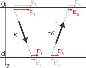
In a similar manner, we also want to couple the amplitudes throughout the layer and we will abuse the labeling used above.

Just below the upper interface, at \(z=0\), the transmitted wave propagates with amplitude \(E_T\) and will acquire a phase factor when reaching the lower interface, where we label the amplitude as \(E’_I\),
\(
\begin{align}
E’_I =E_T e^{ik_0\kappa d}.
\end{align}
\)
And in reverse,
\(
\begin{align}
E’_R =E_B e^{-ik_0\kappa d}.
\end{align}
\)
One thing we shouldn’t overlook is that the film thickness, \(d\), brings actual length scale, so we have to multiply our geometrical component \(\kappa\) with the physical magnitude of vacuum wave vector, \(k_0 = \omega / c\), i.e. the vacuum wave number. It is practical to express this quantitiy directly in the inverse length unit, reciprocal to the length unit used for the thickness.
Again, we want to write the amplitudes “above” as a function of the amplitudes “below”, in a matrix form
\(
\begin{align}
\begin{bmatrix}
E_T \\
E_B
\end{bmatrix}
=
\begin{bmatrix}
e^{-ik_0\kappa d} & 0 \\
0 & e^{ik_0\kappa d}
\end{bmatrix}\cdot
\begin{bmatrix}
E’_I \\
E’_R
\end{bmatrix}\equiv\boldsymbol{\hat{\Phi}}
\begin{bmatrix}
E’_I \\
E’_R
\end{bmatrix}.
\end{align}
\)
We write, for each layer \(j\),
|
\( \begin{align} \boldsymbol{\hat{\Phi}_j}= \begin{bmatrix} e^{-ik_0 \kappa_j d_j} & 0 \\ 0 & e^{ik_0 \kappa_j d_j} \end{bmatrix}, \end{align} \) |
which is here common for both polarizations, since we have isotropic medium.
Matrix for the whole stack
Using the propagation and interface matrices we can now couple the amplitudes throughout the whole multilayer
|
\( \begin{align}\label{eqMatMult} \begin{bmatrix} E_I \\ E_R \end{bmatrix} =\mathbf{\hat{R}}_3\cdot\boldsymbol{\hat{\Phi}}_3\cdot \mathbf{\hat{R}}_2\cdot\boldsymbol{\hat{\Phi}}_2\cdot \mathbf{\hat{R}}_1\cdot\boldsymbol{\hat{\Phi}}_1\cdot \mathbf{\hat{R}}_0\cdot \begin{bmatrix} E_T \\ 0 \end{bmatrix} \equiv\mathbf{\hat{M}}\cdot \begin{bmatrix} E_T \\ 0 \end{bmatrix}, \end{align} \) |
where the incident wave \(E_I\) and the reflected \(E_R\) are traveling in our ellipsometer, while the final transmitted wave \(E_T\) disappears in the semi-inifinite (possibly absorbing) substrate, and there is no wave coming back. Therefore, we can write the reflection coefficient for the whole sample as
|
\( \begin{align} r=\frac{E_R}{E_I}=\frac{M_{21}E_T}{M_{11}E_T}=\frac{M_{21}}{M_{11}}, \end{align} \) |
separately for the p- and s-polarization. Note that \(t=1/M_{11}\), so \(1+r \neq t\) as was the case of single interface.
The described procedure is straightforward, but contains the implicit assumption that the waves propagate throughout the whole stack, so the \(E_T\) is non-zero. There are two possible issues: If some of the layers is so strongly absorbing and thick that no light passes through (corresponding \(\boldsymbol{\hat{\Phi}}\) will have \(\infty\) and \(0\) on the diagonal), or if, due to some special coincidence, a perfect total reflection occurs on one of the interfaces so the \(\kappa_j = 0\). The former is solved by performing the matrix multiplication \eqref{eqMatMult} top-down from the upper interface and stopping at the last interface before the highly absorbing layer. The latter issue is quite interesting and we will come back to that later.
1 The vacuum constants do not appear in our theory, since we work in the Heaviside-Lorentz units.