$\setCounter{0}$
Part 1: The wave vector
Part 2: The interface
Part 3: The s-polarization
Part 4: The p-polarization
Part 5: Multilayers
In the previous posts we’ve shown that Maxwell’s equations support plane waves, only restrict the wave vector. Then we’ve seen that on planar interface between two media, the direction of the wave vector must change, due to continuity of the field components. We work with isotropic medium, so these findings are independent on polarization of the fields.
What we want now, is to find – for given amplitude of the incident wave – the amplitudes of the reflected and transmitted waves. The incoming wave can be in any polarization state, which we can write as linear combination of two orthogonal polarization states. Due to the symmetry of the problem, the obvious choice is two linear polarizations: one with electric field perpendicular to the plane of incidence, called s-polarization (s is from German senkrecht ), or TE (transverse electric); second with electric field parallel to the plane of incidence, p-polarization, or TM (transverse magnetic).
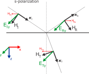
In this blog we will have a look on the s-polarization. Following figure illustrates the situation:

One has to keep in mind that this picture is just schematic and corresponds to the case of simple dielectric with \( \varepsilon > 1 \). Important is that the s-polarized \(\bf{E}\) field has only y-component, so we will measure the field amplitudes in the positive direction of \(y\). We have plotted the magnetic field oriented so the vectors \(\mathbf{E},\mathbf{H},\boldsymbol{k}\) form a right-hand system, as we’ve seen previously. What is not captured in this figure, is the actual relative magnitude of the amplitudes, particularly the fact that the reflected amplitude should be much smaller than the incident and will have opposite sign. This we will see at the end of this post.
For all three waves, the electric field vector will be \( \mathbf{E}_j = (0,E_{j},0) \), where we will drop the index \(y\), and the magnetic field lies in the plane of incidence \( \mathbf{H}_j = (H_{jx},0,H_{jz}) \). The index \( j = I,R,T \) stands for the incident, reflected and transmitted wave.
So for given amplitude \( E_I \) we have two unknown amplitudes \( E_R \) and \( E_T \). The remaining components of the \( \mathbf{H} \) field can be resolved afterwards with the help of equations we already know from the Part 1 and Part 2. What we need here are two equations for conservation of the in-plane components of the \( \mathbf{E} \) and \( \mathbf{H} \), that is
\(
\begin{align}
\begin{aligned}
E_I+E_R &= E_T,
\\
H_{Ix}+H_{Rx} &= H_{Tx},
\end{aligned}\label{eqFieldMatch}
\end{align}
\)
We can divide the first eqation by \( E_I \), getting
\(
\begin{align*}
1+\frac{E_R}{E_I} &= \frac{E_T}{E_I},
\end{align*}
\)
or,
|
\( \begin{align}\label{eqDefCoefs} 1+r_s &= t_s. \end{align} \) |
Here we defined the Fresnel’s coefficients for reflection, \( r_s = E_{Ry}/E_{Iy} \), and transmission, \( t_s = E_{Ty}/E_{Iy} \), for the s-polarization. For clarity I’ve added the index \(y\) back again.
In previous Part 2, equation (3), we have written the wave vectors \( \boldsymbol\kappa_j \). We will insert them into the third Maxwell’s equation in the form of eqs. (9) in Part 1:
\(
\begin{align}
\mu_j\mathbf{H}_j = \boldsymbol\kappa_j \times \mathbf{E}_j = (-\kappa_j E_{jy}, 0 , \xi E_{jy}),
\end{align}
\)
where the index \(j\) signifies that the formula is valid for all three waves, using the corresponding \( \kappa_j \), i.e. \( \kappa_I \equiv q \), \( \kappa_R \equiv -q \) and \( \kappa_T \equiv \kappa \). The components written explicitly read:
\(
\begin{align}
\begin{aligned}
H_{Ix} &= -q E_{Iy},
& H_{Iz} &= \xi E_{Iy},
\\
H_{Rx} &= q E_{Ry},
& H_{Rz} &= \xi E_{Ry},
\\
H_{Tx} &= -\frac{\kappa E_{Ty}}{\mu},
& H_{Tz} &= \frac{\xi E_{Ty}}{\mu},
\end{aligned}\label{eqEHcomponents}
\end{align}
\)
where we remember that \( q = \cos\varphi\) and \( \xi = \sin\varphi\). Then we plug the \( H_{jx} \) components to the second equation of \eqref{eqFieldMatch}, multiply by \( -\mu \), and drop the \(y\) index again, getting:
\(
\begin{align*}
\mu q E_I – \mu q E_R = \kappa E_T.
\end{align*}
\)
Then we replace the \( E_T \) on the right-hand side with first equation of \eqref{eqFieldMatch},
\(
\begin{align*}
\begin{aligned}
\mu q E_I – \mu q E_R &= \kappa E_I + \kappa E_R,
\\
(\mu q – \kappa ) E_I &= (\mu q + \kappa ) E_R.
\end{aligned}
\end{align*}
\)
So the desired \( r_s \) coefficient is
|
\( \begin{align} r_s = \frac{E_R}{E_I} = \frac{ \mu q – \kappa }{ \mu q + \kappa }, \end{align} \) |
and the \( t_s \) is obtained from \eqref{eqDefCoefs}:
|
\( \begin{align} t_s = 1 + r_s = 1 + \frac{ \mu q – \kappa }{\mu q + \kappa} = \frac{ 2 \mu q }{ \mu q + \kappa }, \end{align} \) |
Now we have solved the s-polarization on the interface between vacuum and isotropic \(\varepsilon\mu\) dielectric. The components of the \(\bf{H}\) field are given in eq. \eqref{eqEHcomponents}.
We should note that for simple transparent dielectric with \(\varepsilon > 1 \), \(\mu = 1\), as illustrated on the figure, the \( \kappa > q > 0 \), so the \(r_s\) will be negative and \(|r_s| < 1 \), while the \(t_s\) remains positive.